[here is a 2012 tutorial, outdated, but for the record]
A case study : the epigraphic survey at the Ramesseum
As a member of the French Archaeological Mission to Western Thebes (MAFTO) leaded by Dr. Christian Leblanc, I have been working with Dr. Philippe Martinez, egyptologist and epigraphist, and Kevin Cain, founder and director of INSIGHT, at the implementation of a pipeline involving pointcloud data extraction derived from both Structure from Motion (SfM) and ground truth scanned data. The aim was to benefit from the geometric accuracy of the last one, and from the texture information conveyed by the first one, in order to obtain an accurate 3D textured model that may be used as a trustfully document supporting the epigraphic survey process of the hieroglyphic inscriptions of the temple of Ramses II in Western Thebes (production of orthophotographs from any kind of architectonical components, such as columns, lintels, walls, etc.).
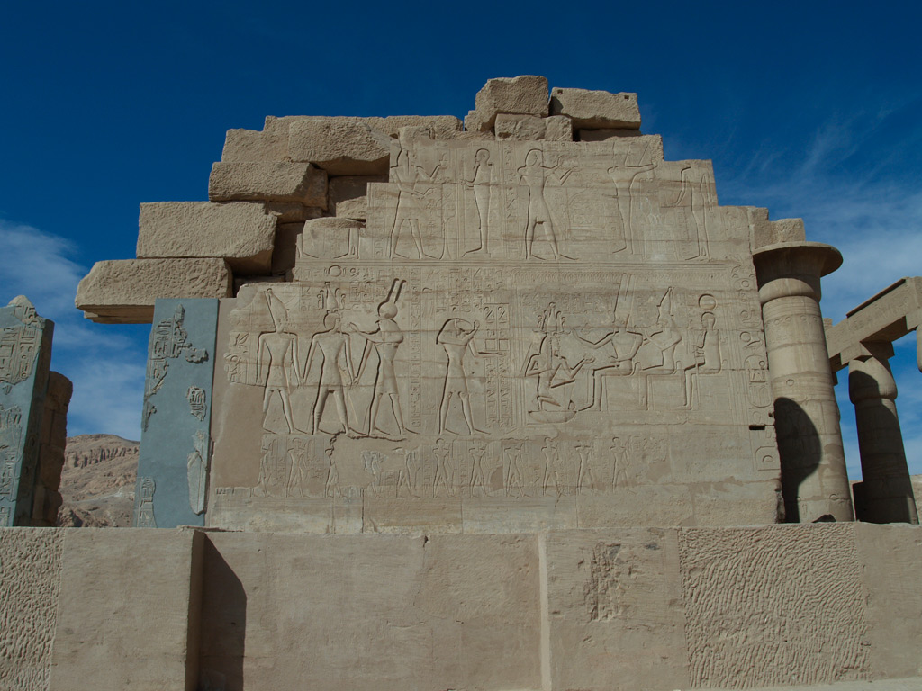
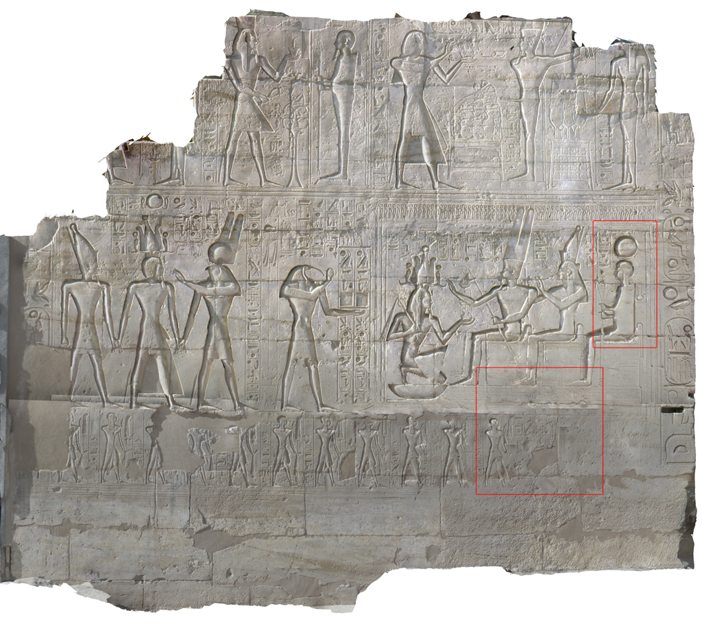
The final idea was to define a fully automatic process to be applied to the whole monument, but for some reasons it wasn’t possible to achieve that point yet know, so we finally managed to propose a partially manual approach which is conceivable to implement. We decided to proceed to an experimentation on the Coronation Scene of the wall located in the Second Court of the Temple of Ramses II.
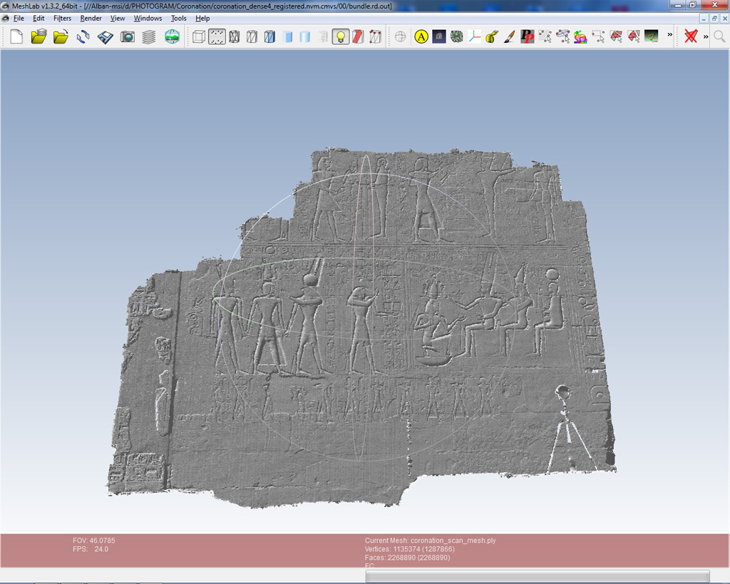
The ground truth pointcloud was provided by INSIGHT. The product used in this tutorial is a mesh generated after a Poisson reconstruction filter has been applied the point set. The SfM 3D reconstruction is derived from a set of photographs taken by Philippe Martinez, Yann Rantier (MAFTO) and Mark Eakle (INSIGHT).
The Structure from Motion toolkit used is VisualSFM (version 0.5.20), developped by Changchang Wu of the University of Washington at Seattle. The dense reconstruction is processed with CMVS/PMVS developped by Yasutaka Furukawa, University of Washington, and Jean Ponce, École Normale Supérieure. The pointcloud and the mesh were displayed and edited with Meshlab (version 1.3.2), developed at the Visual Computing Lab of the ISTI-CNR / University of Pisa (Italy), and we are currently exchanging with Matteo Dellepiane about the implementation of an automatical approach of the processes described below.
For a whole background of this project, please have a look to « A Decade of Digital Documentation at the Ramesseum », available on the INSIGHT website.
N.B. : This experimentation is for me a side project and its outcome will definitively be profitable to my main project, the Archaeological Map of the Western Thebes, that I will present hereby soon.
1. Production of the sparse and dense pointclouds
This part is straightforward and consists in following the steps mentioned in the front page of the VisualSFM website.
- File \ Open + Multi Images or
 (N.B. : Sometimes, with a huge amount of photographs, the software will encounter some difficulties and will fail to load any of the files. A good work around is to load step by step the photographs by smaller sets).
- SfM \ Pairwise Matching \ Compute Missing Match or
 (N.B. : This may take a while, especially with a huge collection of photographs. Therefore it is possible to kill at anytime the pairwise matching process by closing the VisualSFM windows, then launching the software again, loading all the images needed and then resuming the matching process by clicking again the relevant icon. The software will guess automatically how to resume the process. It is to be mentionned also that the software may crash down during an overnight calculation, so whenever possible one has to check if the process is still running).
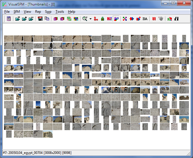
Figure 3. The photographs collection displayed in VisualSFM
- SfM \ Reconstruct 3D or
 (N.B. : After a long lasting calculation, especially if the pairwise matching has been processed just before the reconstruction, it is a good practice to save the result of the reconstruction as an *.nvm file, to have a fresh restart of the system and of the RAM, and then to load the NV match
  before to proceed to the next step).
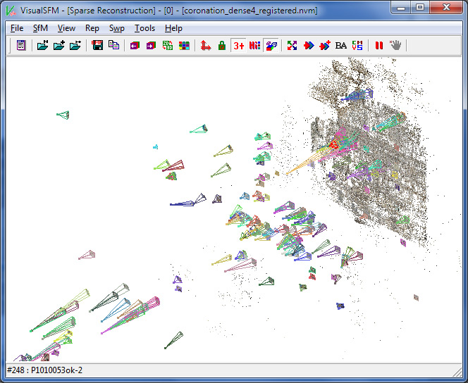
Figure 4. The sparse pointcloud reconstructed and the camera stations displayed in VisualSFM
- SfM \ Run CMVS/PMVS or
 (N.B. : The CMVS/PMVS binary files are not distributed by the developer of VisualSFM 0.5.20, so the user has to collect those softwares from relevant servers). To switch between the sparse and the dense pointclouds, press « TAB ».
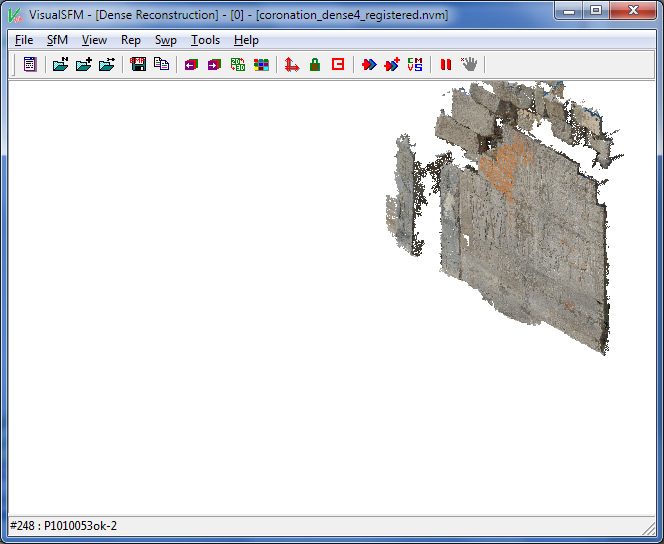
Figure 5. The dense pointcloud reconstructed and displayed in VisualSFM
Some good practices to follow :
- The original or raw photos should be exported to JPEG (best quality) downscaled to 3200 pixels (see the VisualSFM documentation for an explanation).
- If possible, the chromatic aberration should be corrected (i. e. in Adobe Lightroom, Develop \ Activate the profil correction) before exporting the JPEGs. That should increase the number of matched features amongst the photographs set. That said, there is no need to apply a correction to the lense distortion at this time : VisualSFM will allow PMVS to manage it laterly once the cameras parameters are guessed. Meanwhile, it’s also a good idea to set the tone and the white balance settings to automatic.
- For example, the sparse reconstruction can be named [your_file_name]_sparse.nvm
- … and the dense reconstruction can be named [your_file_name]_dense.nvm.cmvs
2. Manual Registration of the SfM reconstructions onto the ground truth pointcloud
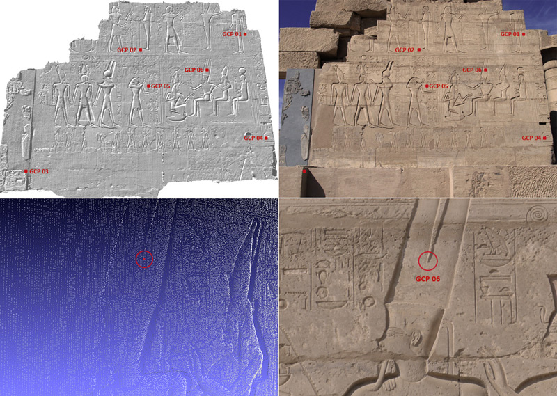
The registration of the SfM pointclouds will be based on some measurements taken on the ground truth pointcloud. Those measurements, the Ground Control Points (GCPs), are to be easily remarkable amongst the ground truth pointcloud and some photographs handled by VisualSFM, and should be selected throughout all the model or scene we want to process. Here I choose 6 GCPs spreaded over the wall.
2.1. Process in Meshlab
- File \ Import Mesh or
 : import the ground truth pointcloud or the mesh in Meshlab.
 - Edit \ Select Vertexes or
 : select ONE vertex which optimically matches the GCP in the photograph.
 - Filters \ Selection \ Invert Selection, uncheck Invert Face, then Apply : Select all the other vertices.
- Filters \ Selection \ Delete Selected Vertices or
 : only the initially selected vertex remains.
 - File \ Export Mesh as ; make sure not to export the source file (in this case, the previous file will be lost), but to export this one vertex file as a new created one to be named like [GCP_ID].ply, then make sure to uncheck Binary Encoding. For example, let’s say that our file is named GCP06.ply
- Redo this process for each GCP.
N.B. : To keep a memory of the location of the GCPs, especially if they are numerous, it’s a good practice to create a modified version of a photograph where the GCP appears, and to enlight its location with a mark, in red for example as shown above, then to name the file from the GCP’s ID. Ex.: GCP06.jpg
2.2. Extraction of the GCPs’ coordinates
2.2.1. Coordinates expressed in a local system
- Open the *.ply file in Notepad or Notepad++. If the *.ply file was correctly exported from Meshlab with the Binary Encoding option unchecked, we should obtain something like that :
ply
format ascii 1.0
comment VCGLIB generated
element vertex 1
property float x
property float y
property float z
element face 0
property list uchar int vertex_indices
end_header
-3379.9 2874.5 -7623.1
As mentioned within the header of the file, there is only 1 vertex, and its coordinates XYZ are listed just after the last line of the header. So for our GCP #6, we know now that its coordinates from the ground truth pointcloud is x = -3379.9 y = 2874.5 and Z = -7623.1
In some case, you may obtain a more detailed *.ply file, like that :
ply
format ascii 1.0
comment VCGLIB generated
element vertex 1
property float x
property float y
property float z
property uchar red
property uchar green
property uchar blue
element face 0
property list uchar int vertex_indices
end_header
-3379.9 2874.5 -7623.1 195 127 97
In this case, this is quite straightforward, the line relevant to our only vertex should be read as described in the header:
x = -3379.9; y = 2874.5; z = -7623.1; Red = 195; Green = 127; Blue = 97, where the RGB values describe the color of the vertex. By the way, we can therefore decide to attribute any kind of RGB value to each of our GCPs to enhanced their visualization in Meshlab and over the native ground truth point cloud, provide the header structure reflects the set of property describing each vertex.
- Eventually, we can create a list or a table with all the GCPs and their relevant XYZ data, which should be kept expressed inline like : X[space]Y[space]Z. Then proceed directly to part 2.3.
N.B. : Obviously, the coordinate of the GCPs would have been more accurately acquired with a Total Station.
2.2.2. Coordinates expressed in a georeferenced system
~~ Under preparation ~~
2.3. Process in VisualSFM
- SfM \ Load NV Match or
 . Open the [your_file_name]_dense.nvm file. Wait until the loading of the pictures, the sparse and the dense reconstructions had been completed (it may take a while). For saving time, it is possible to skip the loading of the image pixel data by Tools \ Terminate Task or
  . Once done, the task viewer should display some lines like :
Loading image pixel data …done in 10s
Loading matching records …done in 54s
—————————————————————-
Load existing N-View match, aborted
Totally 125.000 seconds used
- SfM \ More Function \ GCP-based Transform. Then the main commands of this mode are displayed in the task-viewer. In the viewport, the pointer of the mouse should be stuck with a blue rectangle (while in 3D Match-view mode) or with a green cross (while in Image mode). Here are the commands :
CTRL + Left Click: add or modify a point;
CTRL + Menu Click: clear existing data;
SHIFT + Menu Click: apply transformation.
ESCAPE: quit the point selection mode.
TAB: switch between dense & sparse points.
« Menu » refers to « GCP-based Transform ».
- Navigate in the 3D view to find a photograph in which the GCP we want to register might be seen. To select a photograph, move the mouse over its 3D icon (a coloured wireframed pyramid) and Right double-click (tips : if the pyramid icons are too small in the viewport, CTRL + scrolling the middle-button might help). Once in Image mode, the pointer is stuck with a green cross. A Right double-click on the photograph will lead back to the 3D view mode.
OR
- Navigate in the Thumbnails Mode
 to find a photograph in which the GCP we want to register might be seen (pan, zoom in & out with the mouse). To select a photograph, move the mouse over it and Left double-click. Once in Image mode, the pointer is stuck with a green cross. A Right double-click on the photograph will lead back to the Thumbnails view mode.
- In Image Mode, navigate to find the location of the GCP (pan, zoom in & out), overlay it with the green cross then press CTRL + Left Click. A dialog box will pop-up, asking for its XYZ coordinates. Enter, or Copy and Paste from the *.ply file of the GCP previously opened with Notepad (or the list or table you created). A blue cross should now mark the location of the GCP onto the photograph. It’s still possible to modify the mark by rolling over the blue cross (a blue square should then appear) and by pressing CTRL + Left Click then enter again the value.
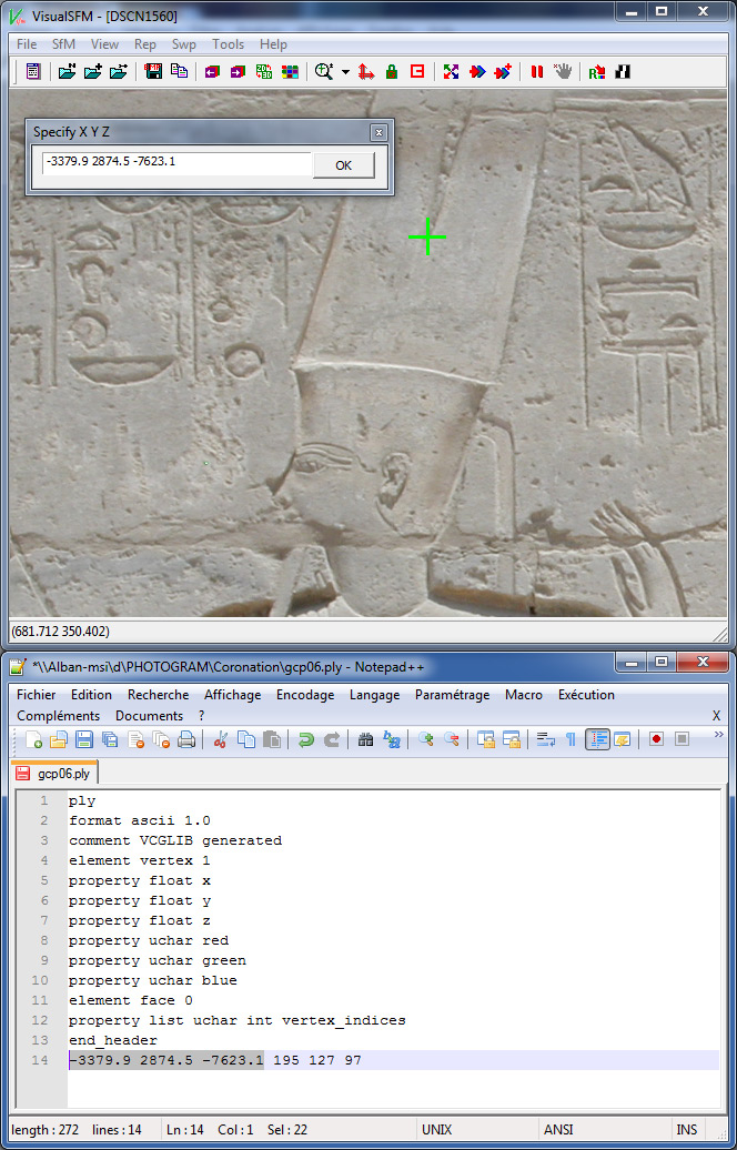
Figure 7. Registration of a GCP in VisualSFM
- Restart this process with one or two other photographs in which the same GCP appears.
- Apply the whole process to the other GCPs, and each time make sure to find and mark two or three differents photographs where each of them appear.
- After the second GCP has been successfully registered, the respective location of each GCP should be shown in the 3D View mode as a red square.
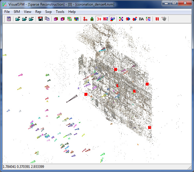
Figure 8. Registered GCPs displayed as red squares in the 3D Viewport of VisualSFM
- After a while, it is always a good idea to save the GCPs, in case of… While still in GCP-based Transform mode, go to SfM \ Save NV Match, and then make sure to give a filename with the extension *.gcp. To recall the GCPs laterly, re-enter the GCP-based transform mode if necessary, and then SfM \ Load NV Match, load the *.gcp file.
- To delete a GCP marked on a photograph, just rollover it, press CTRL + Left Click and close the dialog box without modifying its content (don’t press OK, just click on the « close » icon) .
- It is possible to check the accuracy of the registration process, first, by assessing if the location of the red squares in the 3D sparse pointcloud is trustable (sometimes, you may got mistaken while entering the XYZ value, and the red square will likely to be unappropriately located); secondly, and more accurately, the Root of the Mean Square Error and the Mean Absolute Error are evaluated and displayed in the task viewer after each GCP registration. The idea is to keep these values as small as possible, so any dramatic change or increase should drive your attention and help you to make some correction in the location of the GCP in the intrinsec coordinates of the photograph, or in its extrinsec coordinates.
- Once all the GCPs are trustfully registered and saved in a final *.gcp file (see above), and while still in GCP-based Transform mode, one can press SHIFT + SfM \ More Functions \ GCP-based Transform to globaly apply the transformation to the sparse (with the cameras locations, parameters, etc) and dense reconstructions. The result should appear quickly, and the task viewer should dispay the transformation parameters.
- Then save the result as a new file named [your_file_name]_dense_registered.nvm. Following the size of your scene, it may take a while to save the *.nvm file for the sparse reconstruction, and the *.ply for the dense pointcloud. It is to be mentionned that the dependancies and folder structure created by the CVMS/PMVS aren’t saved nor transformed (cf. below for exporting those data). Only the final and flattened *.ply located at the root of the project is transformed and saved. Once done, then we can exit the GCP-based Transform mode by pressing the Escape key after clicking in the viewport.
3. Preparation, Importation and Display of the registered pointclouds
3.1. Preparation
Before going on this project with Meshlab, we still need to prepare some data from VisualSFM : the bundle.rd.out file containing the sparse reconstruction and the cameras parameters, and the relevant undistorted photographs. As mentioned above, the GCP-based Transform isn’t applicable to those secondary files, so we have to process them. They are created after the user launches a dense reconstruction within VisualSFM.
- Close then restart VisualSFM

- SfM \ Load NV Match or
 . Load the [your_file_name]_dense_registered.nvm
 - SfM \ Run CMVS/PMVS or
 . Name [your_file_name]_dense_registered_export.nvm.cmvs, then let the process run until the command « pmvs2 » appears in the Task-viewer. In other words, you have to KILL the dense reconstruction process (unless you really want to render it again) after all the dependant files and folders have been created, especially the undistorted and renamed versions of the photographs, and of course the bundle.rd.out.
 - Close VisualSFM.
- Press Windows Start (at the bottom left of your screen) and type « cmd » in the field to open a Command Window.
- Navigate to the folder [your_file_name]_dense_registered_export.nvm.cmvs\00\visualize\ where are located all the photographs processed and undistorted by PMVS.
- Type the command dir /on /b *.jpg > list.txt
- Close the Command Window ; a file listing all the photographs contained in the current directory as been created.
3.2. Importation
- Start Meshlab

- File \ Open project or
 ; in the drop down list, select « Bundle Output (*.out) and open the bundle.rd.out contained in the folder [your_file_name]_dense_registered_export.nvm.cmvs\00\
 - Then, when asked « Open image file list« , select the Bundler images list file you previously created (list.txt) in [your_file_name]_dense_registered_export.nvm.cmvs\00\visualize\ . Don’t select camera_v2.txt.
- After a while, according to the size of your scene, the sparse model and all the cameras should have been loaded into Meshlab. On the lower/middle part of the Layer dialog box (here on the right) are listed the photographs.
3.3. Display
- File \ Import Mesh or
 : open [your_file_name]_dense_registered.0.ply (the dense reconstruction), or the ground truth pointcloud/model.
 - View \ Show Current Raster Mode or
 , then double-click on a *.jpg file listed in the Layer panel
  . The photograph selected should be displayed in the viewport and the viewpoint matches the 3D scene. By scrolling the middle-button of the mouse it is possible to play around the overlay of the photograph over the model / pointcloud. A double-click on another jpg of the list will update both the display of the photograph and the viewpoint in the viewport.
Figure 10. Display of the registered rasters over the ground truth model.
4. Preparation and Extraction of the texture
In order to retrieve the texture from the photographs, we will use the Meshlab filter Texture \ Parameterization + texturing from registered rasters. For a quick overview, please watch to Mister P.’s Meshlab tutorial Raster Layers: Parameterization and Texturing from rasters. As it is said in that tutorial, the filter will be successfully applied if there is only a small number of rasters, which is not the case in our project, so we’ll have first to reduce its number through VisualSFM. The idea is to keep only the photographs we need and that convey the expected texture information, and then to export this modified version of the sparse reconstruction.
4.1. Removing the unwanted rasters
- Start VisualSFM

- SfM \ Load NV Match or
 . Load the [your_file_name]_dense_registered.nvm.
 - SfM \ Save NV Match then name the file [your_file_name]_dense_registered_reduced.nvm.
- In 3D View
 , select a camera by pressing Right Click and delete it with the hand icon
  .
.
OR/AND
- Press F1, draw a selection rectangle over several cameras, and press the hand icon
 .
.
OR/AND
- Press F2, draw a selection rectangle over the 3D matches (sparse pointcloud), and press the hand icon
 . The cameras/rasters related to these matches will be deleted. It’s possible to grow the numbers of 3D matches displayed in the viewport by unchecking View \ More Options \ Show 3+ Points or
  , which is activated by default.
OR/AND
- In Thumbnail Mode
 , Right Click on a raster and then press the hand icon
  .
.
THEN
- Once only 10 to 20 registered and necessary rasters are left, prepare a new CMVS/PMVS export as describe above in 3.1. to generate a new folder structure with the bundle.rd.out,list.txt and undistorted *.jpg files. No need to fully run the dense reconstruction.
Addendum :
Matteo Dellepiane has kindly drawn my attention to an alternative method to enable the desired rasters without having to delete them and to generate a reduced version of the sparse reconstruction. So, if the desired registered rasters are known, it is just straightforward to disable them before the application of the Parameterization + texturing from registered rasters filter, which has to be done by unchecking the mark in front of the raster name in the layer dialog box. Many thanks to him for his comment.
4.2. Processing and correcting the mesh
The Meshlab filter Texture \ Parameterization + texturing from registered rasters will only work on a clean triangulated mesh. To ensure the mesh is fine, here are some corrections to apply :
- Start Meshlab

- File \ Import Mesh or
 : open the mesh derived from the ground truth pointcloud.
 - Filters \ Cleaning and Repairing \ Select Non Manifold Edges , then Filters \ Selection \ Delete Selected Faces and Vertices or
 or SHIFT + DEL.
 - Filters \ Cleaning and Repairing \ Select Non Manifold Vertices, then Filters \ Selection \ Delete Selected Vertices or
 or CTRL + DEL.
 - File \ Export Mesh.
- Close Meshlab
4.3. Texture extraction
- Open Meshlab
- Open the bundle.rd.out and the list.txt files located in the [your_file_name]_dense_registered_reduced.nvm.cmvs folder, following the steps described in 3.2.
- File \ Import Mesh or
 : open the corrected and cleaned mesh.
 - Filters \ Texture \ Parameterization + texturing from registered rasters, then, according to your GPU specifications, define an appropriate texture size (512, 1024, 2048, 4096 or more ?). In case the texture size is too big, the filter is likely to crash.
- After a while, and once the filter has been successfully applied, export the textured mesh by making sure the option TexCoord is checked (by default) in the dialog Choose Saving Options for:. A good idea is to name this mesh [your_file_name]_tex.ply.
- Import [your_file_name]_tex.ply, then make sure that Render \ Color \ Per Mesh is checked.
- Optional : it is possible to transfer the color of the texture to the vertex color.
Figure 11. Display of the textured ground truth model.
4.4. Quality of the texture
~~ under preparation ~~
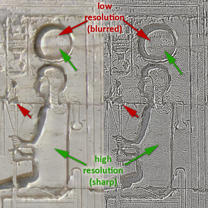
Figure 14. Compositing of several resolution photographs
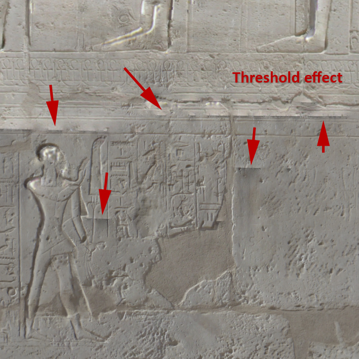
Figure 15. Compositing of several tone / contrast / white balance photographs
5. Comparison of the dense and the ground truth pointclouds
The last point of this tutorial deals with the assessment of the geometric accuracy of the SfM dense model compared to the ground truth data.
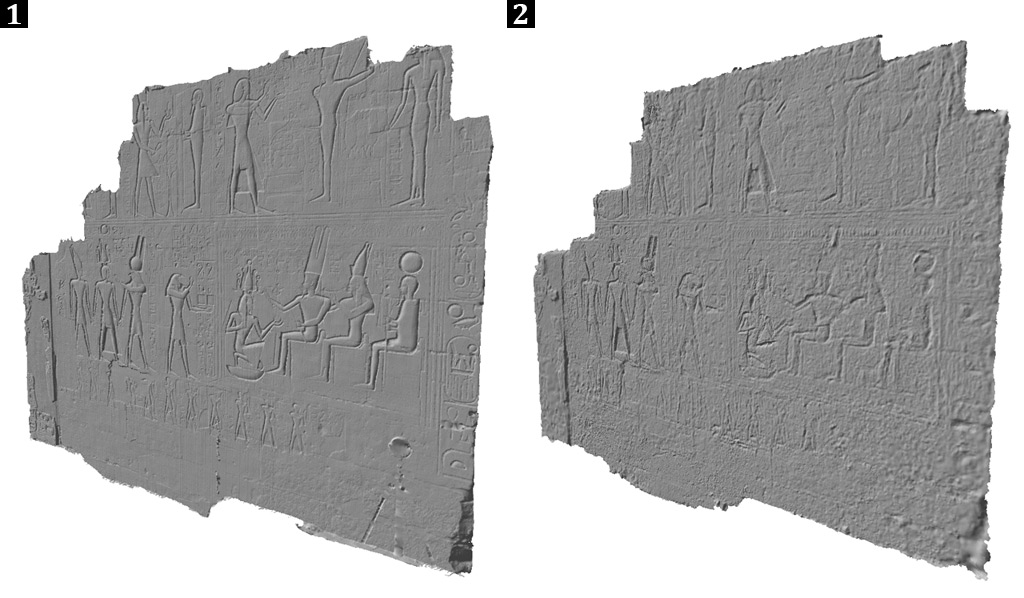
Some screen captures showing the two final meshes viewed in the same conditions are quite eloquent. Although the global structure of the SfM mesh seems to be correct upon an architectural scale (see Fig. 16), the dense reconstruction produces a busy and noisy pointcloud which, even being smoothed after a Poisson reconstruction, fails in retrieving the very details of the wall surface. Especially the depth of the relief is fakely rendered by the shadowed color of the vertices given by the photograph (see Fig. 18.2 & 18.3), without conveying the expected 3D information. At the contrary, the sparser but pretty more regular pointset derived from LiDAR offers a sharper triangulated mesh that is more successful with the documentation of the geometry of the hieroglyphic and reliefs, even if some parts weren’t recorded (i.e. the pseudo-chanfered edges shown in Fig. 18.5), being in a shadowed coverage area and are therefore wrongly triangulated.
Figure 17. Comparison of the ground truth and SfM textured meshes.
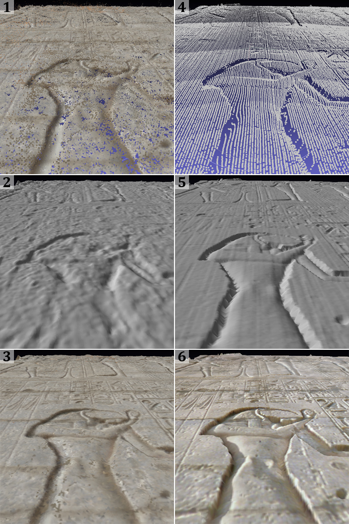
Figure 18. Comparison of the SfM (1-3) and ground truth (4-6) pointclouds and derived meshes.
In order to estimate the differences between the two models, we are applying a global comparison between the two meshes following the method explained in this off-site tutorial Measuring the difference between two meshes part 1 and part 2.
- Start Meshlab

- File \ Import Mesh or
 : open the meshes to be compared.
 - Filter \ Sampling \ Hausdorff Distance, select the Ground truth mesh as Sampled Mesh, and the SfM mesh as Target Mesh, then check Save Samples and Sample Vertices. A Hausdorff Sample Point new mesh should have been created and colored with a red/yellow/green gradient, where red shows the closest vertices and green the farest vertices. If the gradient is to smooth or continuous, it is possible to increase its contrast by :
- Filter \ Color Creation and Processing \Colorize by vertices quality, and play around the settings, especially Percentile Crop.
Figure 18. Application of the Hausdorff Distance filter. Blue areas illustrate a significant discrepancy between the two meshes. Red ones are the more convergent.
Here are the statistics of the filter applied, the units are expressed in millimeters.
min : 0.000000 max 227.992859 mean : 6.822711 RMS : 11.655860
Values w.r.t. BBox Diag (14169.060547)
min : 0.000000 max 0.016091 mean : 0.000482 RMS : 0.000823
The Bounding Box Diagonal (BBox Diag) gives us the rough dimensions of our scene, around 14 meters (the length of the wall measured at its bottom is around 10,82 meters), and the Root Mean Square error (RMS) signifies that we have a bit more of 1 cm of discrepancy between the two meshes, which is very satisfactory for recording the global shape of the wall on an architectural point of view, but of course not enough for documenting the hieroglyphics. As shown in Fig. 18, the Hausdorff Distance surprisely witnesses a ring effect for the very convergence of the vertices (in red, ca. 2 mm of discrepancy), while the most part of the wall shows a yellow to green gradient (ca. 14 mm of discrepancy), and the less accurate records, the few blue spats (ca. 26 mm), are located in the hollow parts, where the shadows casted by the sun are the most likely to vary amongst a huge set of photographs taken at different daytime (see Fig. 19).
Figure 19. Different lighting conditions through the collection of photographs regarding the Hausdorff Distance.
6. Discussion
7. Conclusion
Acknowledgements
References
- Y. Furukama, J. Ponce, « Accurate, Dense, and Robust Multi-View Stereopsis », Pattern Analysis and Machine Intelligence, Volume 32, Issue 8, 2010, pp. 1362-1376.
- P. Cignoni, M. Calliri, M. Corsini, M. Dellepiane, F. Ganovelli, G. Ranzuglia, « Meshlab : an Open-Source Mesh Processing Tool », Sixth Eurographics Italian Chapter Conference, 2008, pp. 129-136. [URL]
- M. Corsini, M. Dellepiane, F. Ganovelli, R. Gherardi, A. Fusiello, R. Scopigno, « Fully Automatic Registration of Image Sets on Approximate Geometry », International Journal of Computer Vision, 2012. [URL]
- J.-M. Frahm, P. Georgel, D. Gallup, T. Johnson, R. Raguram, Ch. Wu, Y.-H. Jen, E. Dunn, B.Clipp, S. Lazebnik, M. Pollefeys, « Building Rome on a Cloudless Day », ECCV 2010, [URL]
